Renewal of Kirchhain Railway Station
Kirchhain station is in the central regional area of DB Station&Service AG and is managed by Gießen station management. It's been assigned station category 4, i.e. it is heavily frequented by local traffic, and, with tracks 801, 802 and 805, is on the 3900 Kassel Hbf-Frankfurt (Main) Hbf route. Mailänder Consult GmbH used the card_1 module Platform Generator to plan the outer and middle platforms.


Although this is not a BIM project by DB Station&Service AG, Mailänder Consult recognised the advantages of the new BIM working method and used it to plan the outer and middle platforms. The new card_1 Platform Generator module was used for this. This enabled the platform to be properly calculated in card_1 and then transferred to Revit for further processing. Likewise, the possibility arose for Mailänder Consult, as in conventional planning, to generate cross-sections and topographic data from the Platform Generator and to generate specification-based drawings.
Calculating Railway Platform Edges
Before the platform can be constructed, the distances/offsets and heights of the platform edge must be precisely determined. To do this the Platform Generator uses width strings. The new module automatically generates these as a template so that they can then be processed further manually. Two width strings are used. One to calculate the offset from the alignment and another to determine the height difference to the vertical alignment. It should be noted that the distances and heights, including widenings, must be calculated correctly according to RIL 813.
Calculating Platform Surfaces
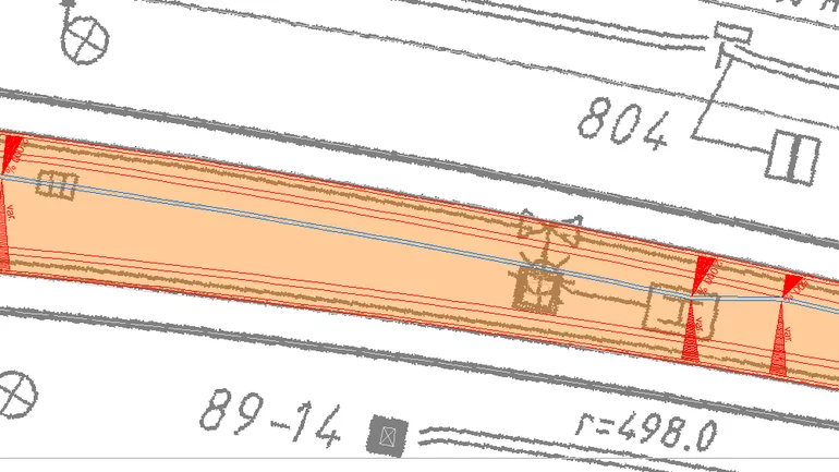
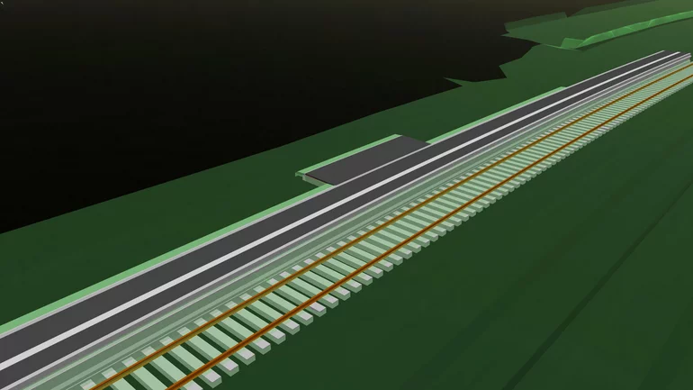
The Platform Generator uses break points to calculate the cross falls of the outer and central platforms. These can be placed at any gradient and distance from the edge of the platform. The platform generator also makes it possible to calculate widenings. The central platform was a challenge in this project. Due to the banked tracks and the small radii, there was a large difference in height between the left and right edge of the platform. This difference in height was quickly and optimally adjusted by iterative generation of the platform with different parameters, without exceeding the maximum value of the cross fall of 2.5%. The connection to the existing outer platform was achieved through the flexible selection of different components. In this way, the first part of the platform could be completed with an angled retaining wall and the second part with a low curb.
Generating Drawings
The Platform Generator creates cross sections and structures in card_1. The module produces a planning cross-section line with unique numbering of the points depending on the object, which can be used with the card_1 function Generate Topography from Cross-sections. If the user defines a process adapted to the Platform Generator in this function, all relevant topographic lines of the platform can be generated immediately. This function can also be used to create slope hachures. With these features, Mailänder Consult had all the basics required for the Kirchhain station platform planning project to create base map and cross-section drawings using classic card_1 specifications.
Transfer to Revit
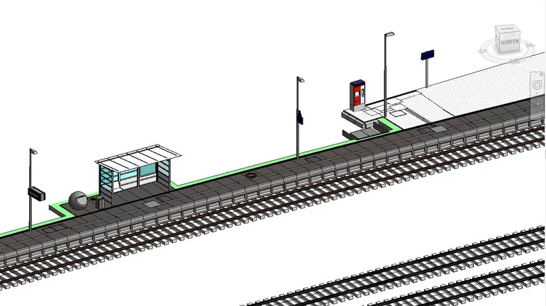
After successfully completing the calculation of the platform in card_1, the platform was transferred to Dynamo using .xls files. The component catalogs of DB Station&Service AG, also called families in Revit, were placed along the construction lines of the Platform Generator in Revit using the Dynamo script developed by Mailänder Consult. Then the modeling of the furniture and the adjustment of the model in Revit was completed.
Calculation of Setting-out Points
After the furniture had been completely placed in Revit, it could be imported back into card_1 in the DXF format. The Mailänder Consult then placed the setting-out points for the surface elevation plan using this DXF file. To calculate the heights of the setting-out points, a planning DTM was generated from the planning line of the Platform Generator using the Generate DTM from Cross-sections function. The calculation of the setting-out points of the platform edge is carried out using a tool integrated in the Platform Generator. There, the setting-out points were clearly determined by a chainage list and placed at the relevant transitions (e.g. widening sections or master alignment points). The Platform Generator also creates a list of setting-out points. The points generated in card_1 were then transferred to the surveyor as an ASCII file.
Contractor:
Mailänder Consult GmbH
Mathystraße 13
76133 Karlsruhe
Fon: +49 721 9328 00
E-Mail to Mailänder Consult
www.mic.de