Noise Barriers for card_1
Model creation is becoming increasingly important in early planning phases as it accelerates decision-making processes. It makes all the more sense to use CardScript to check whether data from other software solutions can be used to “quickly” build specialist models.

Everyone wants BIM – right from the get-go
BIM is now the go-to methodology contractually required in the very early phases of traffic system design. At this stage it is more about the spatial representation of alternatives serving as decision-making aids for design sub-sections rather than about levels of detail or attributes. The following rule of thumb applies: the more detailed a model is, the more meaningful it is for decision-making.
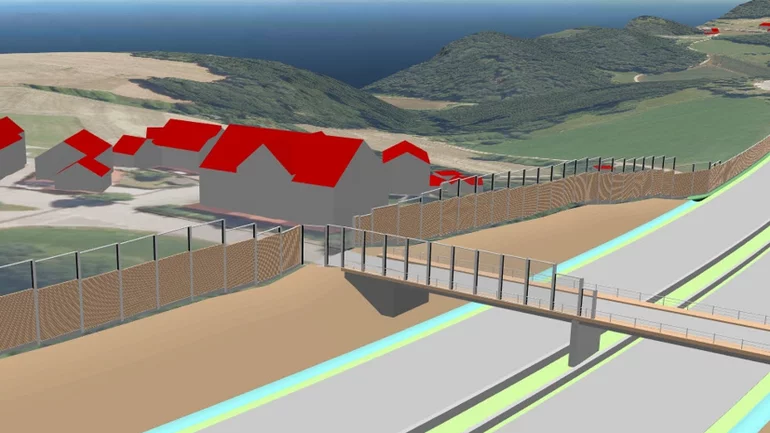
It is clear that in addition to displaying traffic systems, noise barriers may also be required in a model to evaluate alternatives, as they are a spatially defining design element. The representation of noise barriers in a coordination model makes sense both for initial noise-related assessments and for testing the suitability of various noise protection alternatives.
Is it worth investing the time and energy early on?
When creating specialist models, a detailed cost-benefit analysis is of utmost importance. Modeling noise barriers with suitable software such as Revit is time-consuming, and this cost increases with the number of noise barriers to be modelled. The time required to create a model in the early planning phases or explore alternatives must therefore remain within reasonable limits. This is best achieved through automation.
When automated work processes are required, card_1 has the perfect solution: CardScript. As part of a project on noise assessment, we have developed a CardScript that creates noise barrier models and can be extended as required.
Using existing data for noise barrier models
The input data for the model, both for the geometry and for attribution, is actually already available and comes from noise calculation software - in this example from SoundPLAN from the company SoundPLAN GmbH:
- 3D polyline with the post coordinates and wall base point heights
- Heights of the individual wall elements
- Absorption properties as an indication of an opaque or transparent wall element
- Individual lengths and areas of the wall elements
Evaluating the geometry data from SoundPLAN
First, the data for the noise barriers must be compiled in SoundPLAN using a so-called expert table. The data from this table is imported into card_1 to an LIS control file of the alignment along which the wall is to be positioned. The script accesses this list file when creating the part of the model involving the noise barrier and converts the information into components.
Once the noise barrier geometry has been defined for the calculation in SoundPLAN, creating this section of the model in card_1 only takes a few moments.
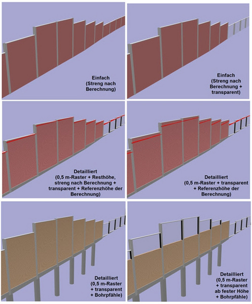
The noise barrier can be exported in different geometries and colours, depending on the desired level of detail:
- Simple wall with height strictly according to calculation
- Detailed wall with base, noise barrier elements and partial or fully transparent parts and drilled piles
- Transparent walls on other structures
- Upper limit of the minimum wall height according to the noise protection calculation
The wall elements are attributed according to the input data. This includes the following elements:
- Description of component group, component and component type
- Element length, element height and area
- If required, the proportion of opaque to transparent parts
- Total length and total area for cost determination
The scope of the attributes and the attribute variables are chosen at random and are purely FYI. The model does not replace the structural design of the noise barrier, in which the model attributes specified in the BEP (BIM execution planning) apply.
This, in conjunction with other specialist models, generates clear 3D graphics – ideal as a checking/coordination tool or as part of suitability studies showing all noise protection alternatives (incl. calculation results: see article p.16f interAktiv issue 02/2019) as specialist models, which can be inserted into the coordination models.
The noise barrier models offer a wide range of possible uses thanks to IFC export.
In addition, the script creates the top edge of the noise barrier as a ground profile line which can be added to the profile view, making manual editing unnecessary. This takes us full circle back to conventional 2D design.
In Short
If it happens fast it’s worth it... Our experience shows that the BIM methodology is all about automation rather than effort.
In no time at all it was clear that displaying the noise barriers in detail in the models accelerated the coordination process and that spending the time creating the script was well worth it.
Contractor:
Kocks Consult GmbH
Beratende Ingenieure
Stegemannstr. 32 - 38
56068 Koblenz
E-Mail to Kocks Consult GmbH
www.kocks-ing.de