Building the 4th Elbe Tunnel Tube
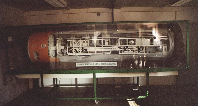
The acronym TRUDE means, in German, "Tief runter unter die Elbe" (deep down under the Elbe). Trude is the biggest shield-tunnelling machine worldwide with a diameter of 14.20 m. It drilled its way under the Elbe from south to north with a soil cover of between 7 and 13 m.
One of the many eventualities for which precautions had to be taken was that Trude would not be able to follow the defined trajectory exactly.
Differences from the theoretical position
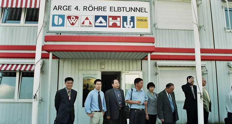
Contracted by ARGE 4. Röhre Elbtunnel ("4th Elbe Tunnel" consortium), the Hamburg engineering office Kallich & Partner developed a system with which the expected differences from the theoretical positions could be visualized when driving through the tunnel. Whenever these differences exceeded the permissible tolerances, a new spatial route had to be recalculated immediately. These recalculations included corrections in order to then stay within the road design tolerances during the subsequent drilling process.
In order to compensate for the expected differences, the plan was to survey the actual tunnel centre line points and from there to create a digital terrain model. The actual centre points were then to be compared to their theoretical counterparts.
To make things more complicated there was only the spatial data for the carriageway alignment available but not for the alignment along which Trude should be drilling. Furthermore this alignment related to the carriageway alignment but with continuously changing offsets.
Problem solved with card_1 Cross-Section Design
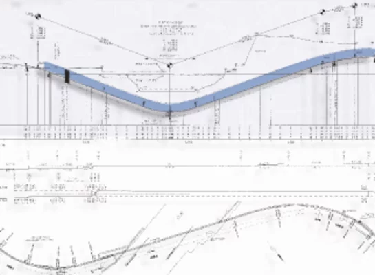
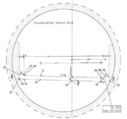
The problem was solved using the card_1 cross-section design package. The planned carriageway alignment defined by the carriageway centre line including a hard shoulder, its cross-fall and the vertical alignment was used as the data basis for the system. Together with cross-sections defining the clearance space, the tunnel alignment was then modelled. In order to visualize the differences between the actual positions and their theoretical counterparts, these values were output to width files.
This data was displayed as strings in longitudinal profile drawings. The differences determined were checked against the road design tolerances and compensated for by making changes to the carriageway alignment and/or the vertical alignment. All cross-sections within the affected section had to be then recalculated. The already existing shell of the section had to be checked for any follow-up changes. The overall approach was tested using simulated and random differences within the range from 5 to 15 cm. The results were more than satisfactory.
Executing the plan
During the detailed planning of the tunnel-boring machine Trude, ARGE 4. Röhre chose a slightly bigger diameter than planned in the design. Thus minor differences of the cross-sections from their theoretical position could be compensated for within this bigger shell without having to change the road which was based on the road design and the special vertical alignment. The driving process with Trude was executed so true-to-cross-section that the theoretical positions could be met with the accuracy required. In the end, the carefully prepared compensation process was not needed. A masterpiece of engineering.
